LT3570
13
3570fb
into a tight local loop, minimizing EMI. The input capaci-
tor must have low impedance at the switching frequency
to do this effectively and it must have an adequate ripple
current rating. The RMS input current is:
I
IN2(RMS)
=I
OUT2
"
V
OUT2
V
IN2
V
OUT2
(
)
V
IN2
<
I
OUT2
2
and is largest when V
IN2
= 2 " V
OUT2
(50% duty cycle).
Considering that the maximum load current is ~1.5A, RMS
ripple current will always be less than 0.75A.
The high frequency of the LT3570 reduces the energy
storage requirements of the input capacitor, so that the
capacitance required is often less than 10糉. The combi-
nation of small size and low impedance (low equivalent
series resistance or ESR) of ceramic capacitors makes
them the preferred choice. The low ESR results in very
low voltage ripple. Ceramic capacitors can handle larger
mag nitudes of ripple current than other capacitor types
of the same value. Use X5R and X7R types.
An alternative to a high value ceramic capacitor is a lower
value along with a larger electrolytic capacitor, for ex ample
a 1糉 ceramic capacitor in parallel with a low ESR tantalum
capacitor. For the electrolytic capacitor, a value larger than
10糉 will be required to meet the ESR and ripple current
requirements. Because the input capacitor is likely to see
high surge currents when the input source is applied,
tantalum capacitors should be surge rated. The manu-
facturer may also recommend operation below the rated
voltage of the capacitor. Be sure to place the 1糉 ceramic
as close as possible to the V
IN2
and GND pins on the IC
for optimal noise immunity.
A nal caution is in order regarding the use of ceramic
capacitors at the input. A ceramic input capacitor can
combine with stray inductance to form a resonant tank
circuit. If power is applied quickly (for example by plug ging
the circuit into a live power source), this tank can ring,
doubling the input voltage and damaging the LT3570. The
solution is to either clamp the input voltage or dampen the
tank circuit by adding a lossy capacitor in parallel with the
ceramic capacitor. For details, see Application Note 88.
Boost Input Capacitor Selection
The capacitor of a boost converter is less critical due to
the fact that the input current waveform is triangular and
does not contain large squarewave currents as found in
the output capacitor. Capacitors in the range of 10糉 to
100糉 with an ESR of 0.3?or less work well up to the
full 1.5A switch current. Higher ESR capacitors may be
acceptable at low switch currents. Input capacitor ripple
current for boost converters is:
I
RIPPLE
=0.3"V
IN1
"
V
OUT1
V
IN1
f"L"V
OUT1
Buck Diode Selection
The catch diode (D2 from Figure 1) conducts current only
during switch-off time. Average forward current in normal
operation can be calculated from:
I
D(AVG)
=I
OUT1
"
V
IN1
V
OUT1
V
IN1
The only reason to consider a diode with a larger current
rating than necessary for nominal operation is for the
worst-case condition of shorted output. The diode current
will then increase to the typical peak switch current.
Peak reverse voltage is equal to the regulator input volt age.
Use a diode with a reverse voltage rating greater than the
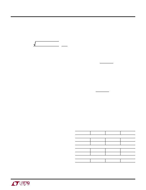
input voltage. Table 3 lists several Schottky diodes and
their manufacturers.
Table 3. Schottky Diodes
PART NUMBER
V
R
(V)
I
AVE
(A) V
F
AT 1A (mV)
On Semiconductor
MBRM120E
20
1
530
MBRM140
40
1
550
Diodes Inc.
B120
20
1
500
B130
30
1
500
International Recti er
10BQ030
30
1
420
APPLICATIONS INFORMATION
发布紧急采购,3分钟左右您将得到回复。
相关PDF资料
LT3645HMSE#TRPBF
IC REG DL BUCK/LINEAR 12-MSOP
LT3694IFE-1#TRPBF
IC REG TRPL BUCK/LINEAR 20TSSOP
LT4220IGN#TR
IC CTLR HOTSWAP DUAL 16-SSOP
LT4250LCN8
IC CONTRLR HOT SWAP NEG 48V 8DIP
LT4254CGN
IC CTRLR HOTSWAP POSVOLT 16SSOP
LT4256-1IS8#TRPBF
IC CTRLR HOTSWAP HV LATCH 8SOIC
LTC1392IS8#TRPBF
IC DATA ACQ SYSTEM 10BIT 8-SOIC
LTC1421ISW-2.5#PBF
IC CONTROLLER HOT SWAP 24-SOIC
相关代理商/技术参数
LT3570IFE-PBF
制造商:LINER 制造商全称:Linear Technology 功能描述:1.5A Buck Converter, 1.5A Boost Converter and LDO Controller
LT3570IFE-TRPBF
制造商:LINER 制造商全称:Linear Technology 功能描述:1.5A Buck Converter, 1.5A Boost Converter and LDO Controller
LT3570IUF#PBF
功能描述:IC REG TRPL BCK/BST/LINEAR 24QFN RoHS:是 类别:集成电路 (IC) >> PMIC - 稳压器 - 线性 + 切换式 系列:- 标准包装:2,500 系列:- 拓扑:降压(降压)同步(3),线性(LDO)(2) 功能:任何功能 输出数:5 频率 - 开关:300kHz 电压/电流 - 输出 1:控制器 电压/电流 - 输出 2:控制器 电压/电流 - 输出 3:控制器 带 LED 驱动器:无 带监控器:无 带序列发生器:是 电源电压:5.6 V ~ 24 V 工作温度:-40°C ~ 85°C 安装类型:* 封装/外壳:* 供应商设备封装:* 包装:*
LT3570IUF#TRPBF
功能描述:IC REG TRPL BCK/BST/LINEAR 24QFN RoHS:是 类别:集成电路 (IC) >> PMIC - 稳压器 - 线性 + 切换式 系列:- 标准包装:2,500 系列:- 拓扑:降压(降压)同步(3),线性(LDO)(2) 功能:任何功能 输出数:5 频率 - 开关:300kHz 电压/电流 - 输出 1:控制器 电压/电流 - 输出 2:控制器 电压/电流 - 输出 3:控制器 带 LED 驱动器:无 带监控器:无 带序列发生器:是 电源电压:5.6 V ~ 24 V 工作温度:-40°C ~ 85°C 安装类型:* 封装/外壳:* 供应商设备封装:* 包装:*
LT3570IUF-PBF
制造商:LINER 制造商全称:Linear Technology 功能描述:1.5A Buck Converter, 1.5A Boost Converter and LDO Controller
LT3570IUF-TRPBF
制造商:LINER 制造商全称:Linear Technology 功能描述:1.5A Buck Converter, 1.5A Boost Converter and LDO Controller
LT3571EUD#PBF
功能描述:IC REG BOOST ADJ 0.47A 16QFN RoHS:是 类别:集成电路 (IC) >> PMIC - 稳压器 - DC DC 开关稳压器 系列:- 标准包装:250 系列:- 类型:降压(降压) 输出类型:固定 输出数:1 输出电压:1.2V 输入电压:2.05 V ~ 6 V PWM 型:电压模式 频率 - 开关:2MHz 电流 - 输出:500mA 同步整流器:是 工作温度:-40°C ~ 85°C 安装类型:表面贴装 封装/外壳:6-UFDFN 包装:带卷 (TR) 供应商设备封装:6-SON(1.45x1) 产品目录页面:1032 (CN2011-ZH PDF) 其它名称:296-25628-2
LT3571EUD#TRPBF
功能描述:IC REG BOOST ADJ 0.47A 16QFN RoHS:是 类别:集成电路 (IC) >> PMIC - 稳压器 - DC DC 开关稳压器 系列:- 标准包装:2,500 系列:- 类型:降压(降压) 输出类型:固定 输出数:1 输出电压:1.2V,1.5V,1.8V,2.5V 输入电压:2.7 V ~ 20 V PWM 型:- 频率 - 开关:- 电流 - 输出:50mA 同步整流器:是 工作温度:-40°C ~ 125°C 安装类型:表面贴装 封装/外壳:10-TFSOP,10-MSOP(0.118",3.00mm 宽)裸露焊盘 包装:带卷 (TR) 供应商设备封装:10-MSOP 裸露焊盘